
When the Precision Time Protocol (PTP) is used for time synchronisation, the equipment between the grandmaster and the clients can reduce the overall accuracy of the system. In a previous blog article, we looked at how the transparent clock limits this phenomenon. The boundary clock does not work in the same way as the transparent clock. It does not merely allow PTP messages through by correcting them. It serves as a local time reference for the clients, while remaining synchronised with the grandmaster.
The delay accumulation problem
When a PTP message passes through a switch, it is placed in a queue with the rest of the network traffic. The transit time in this switch depends on the network load at that precise moment, and therefore varies from one message to another. This variation, which is known as PDV (Packet Delay Variation), distorts the synchronisation calculation, therefore affecting the time precision. More problematic still is that PDV accumulates with each piece of equipment passed through: after a few hops, PTP is therefore no more precise than NTP.
The role of the boundary clock is to address this problem by cutting the delay accumulation chain into several segments. These segments will then be synchronised independently.

Reliable synchronisation for your critical environments
Provide accurate and consistent synchronisation across all your equipment, without any drift.
How does a boundary clock work
A boundary clock is a piece of equipment with several PTP ports and performs two roles simultaneously. On one of its ports, the client port, it synchronises with the grandmaster as any client would. On its other ports, the server ports, it redistributes this synchronised time to the equipment downstream, thus serving as a local time reference.
A boundary clock therefore separates the PTP chain into two distinct segments. Upstream, it behaves like a client, downstream, like a server. The clients located after it no longer communicate directly with the grandmaster. Instead, the boundary clock is their immediate time reference.

The delay variations accumulated between the grandmaster and the boundary clock remain confined to the upstream network segment. The clients (downstream) benefit from their own synchronisation. Each segment therefore has its own delay evaluation, and the PTP signal is “regenerated” at each boundary clock (hence its name).
Why use a boundary clock?
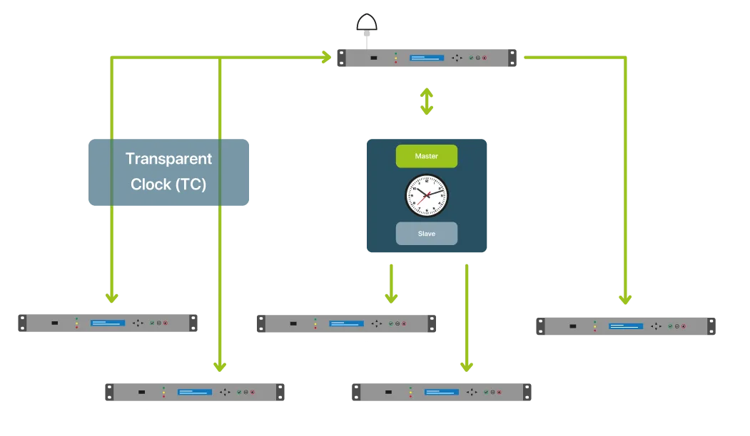
Using boundary clocks ensures the reliability of the time distribution on large networks. With transparent clocks, all of the clients communicate directly with the grandmaster, which ends up becoming saturated if there are too many clients. The boundary clock spreads this load: each PTP switch takes care of a subset of clients, and the grandmaster communicates exclusively with the first-level boundary clocks. The architecture becomes tiered, with each level only managing a limited number of sessions.
By design, the boundary clock principle divides the network. The synchronisation can therefore be cut down into independent zones, each with its own local reference. Deployment, diagnostics and maintenance are much simpler as a result.
When is a boundary clock not suitable?
The boundary clock is a clock in its own right. It has its own oscillator, which drifts over time. PTP messages from the grandmaster correct it continuously, but there is still a residual deviation between its internal time and the reference time. However, this deviation adds up at each level: in a three-level architecture, the end clients inherit the sum of the deviations of the three clocks before them. It is therefore better to limit the number of stages to keep this accumulation under control.
This is precisely where the transparent clock maintains an advantage. Since it does not distribute the time itself, it introduces no additional deviation.
When should it be used?
It is particularly useful when the network is vast and there are a large number of clients. Conversely, on a moderately sized network, with only a few hops between the grandmaster and the clients, the transparent clock is generally enough and is simpler to implement.
In practice, the two are often combined. Boundary clocks are placed at the structuring points of the network, whereas transparent clocks are placed where there are few hops. This hybrid architecture is more common in PTP applications.
Important points regarding installation
In the same way as for the transparent clock, PTP messages must be timestamped at hardware rather than at software level, so as not to lose the precision sought. The quality of the on-board oscillator is also a key factor: a more stable oscillator results in less of a deviation between two corrections, and therefore greater precision for the downstream clients.
The configuration is also worth examining. The PTP ports must be correctly declared (client port facing the grandmaster, server ports facing the clients) and the PTP profile must remain consistent throughout the chain.
One final point: the boundary clock does not correct network asymmetry, i.e., the difference in delay between the message’s outbound journey and inbound journey. This is an issue of network topology and is to be dealt with irrespective of the type of clock used.


